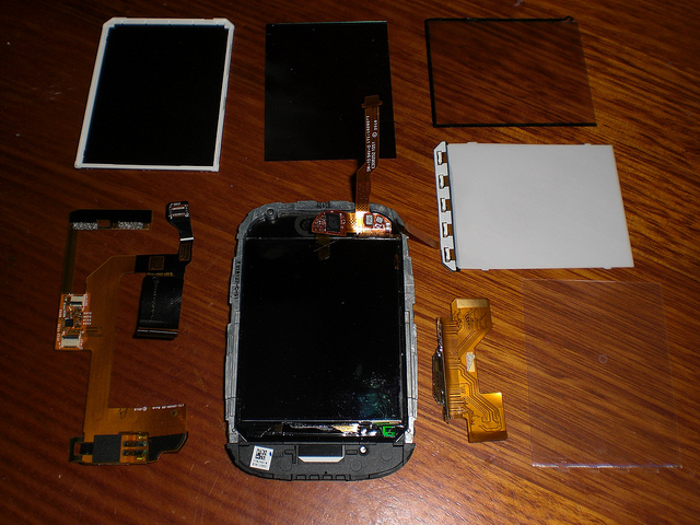
Veer Disassembly
Copyright and Donations
Copyright Notice: All images on this page are copyright by Rod Whitby, with all rights reserved.
An off-contract device purchased at full price ($550 including shipping to Australia) by Rod Whitby was used in this tear-down. To recoup that cost, your PayPal donation is requested.
<paypal></paypal>
Further pictures of the internals of the Veer (including high resolution shots of the circuit boards) will be added to this page as they are taken.
If you wish to use any of these images in any way, please contact @webosinternals on Twitter.
AnandTech and Engadget have been granted a license to use any images from this page (with attribution).
The HP Veer
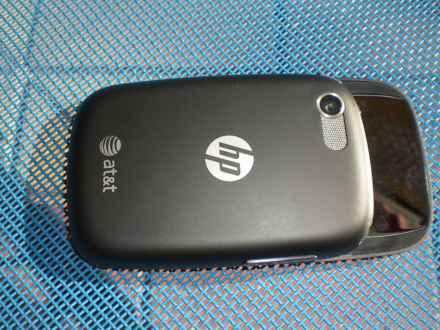
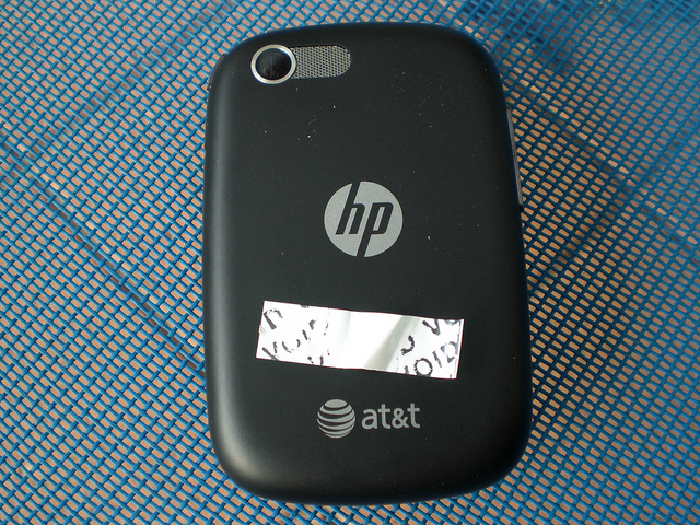
First, here is the rear of the device before disassembly starts. As you can see, it's an AT&T Veer.
To be very clear, this is a device which was purchased at full price off-contract from an AT&T store. There are no strings attached to this device. It was not a free or discounted developer device. The device did not come from HP. There is no NDA, embargo, convenant, or other restriction on this device.
It was used to test Preware, Impostah, Govnah, and other homebrew applications for the Veer. All that was very successful, and I can report that all tested homebrew applications and patches ran safely and correctly on the Veer.
Then it was used for further hard-core command-line investigation into the new "tap to share" interface (which seems to be controlled by an "A6" chip). That's when things went wrong, and the device was permanently bricked. To prevent this happening to you, stay away from the PmA6Updater binary.
Hence there are no qualms in dismantling it. So that we shall do now ...
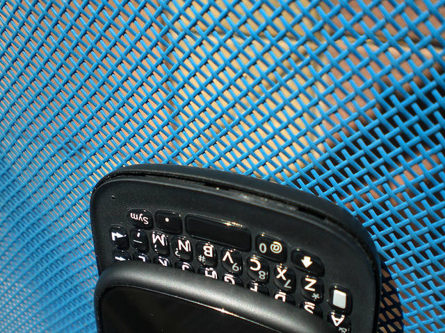
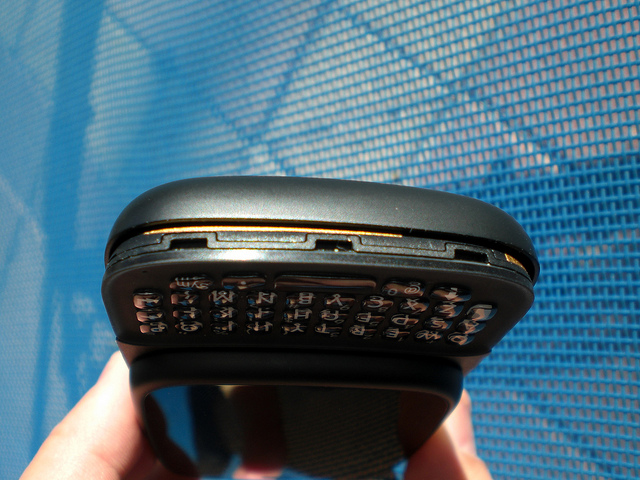
Initial keyboard separation
Separate the plastic around the bottom of the keyboard and the sides of the phone using your fingernail or a spudger.
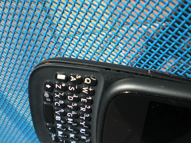
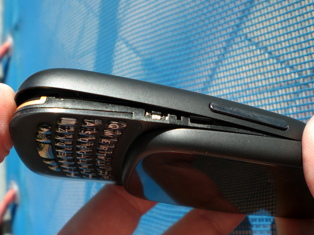
Initial lower half separation
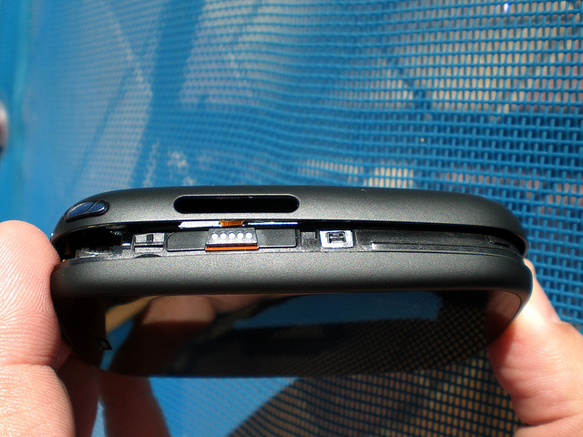
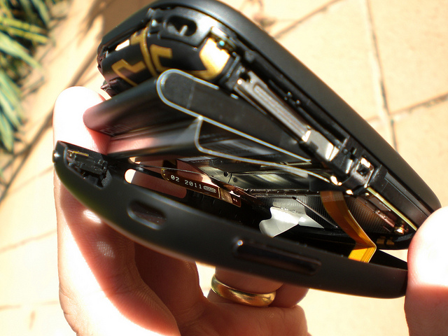
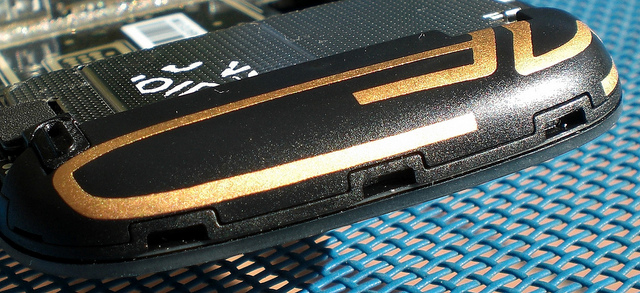
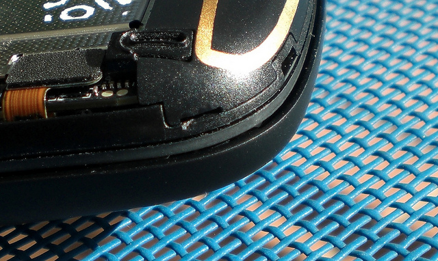
Further separate the backplate at the bottom of the phone and along the sides, but do not pull it any further apart than this.
Note that the volume rocker switch is part of the backplate ...
... but the magnetic connector is not.
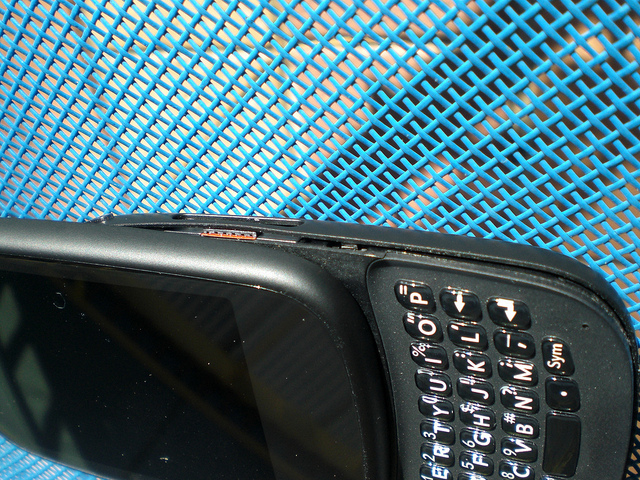
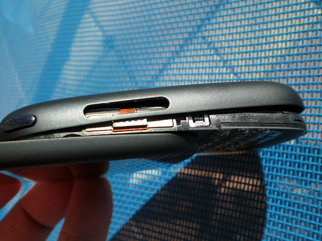
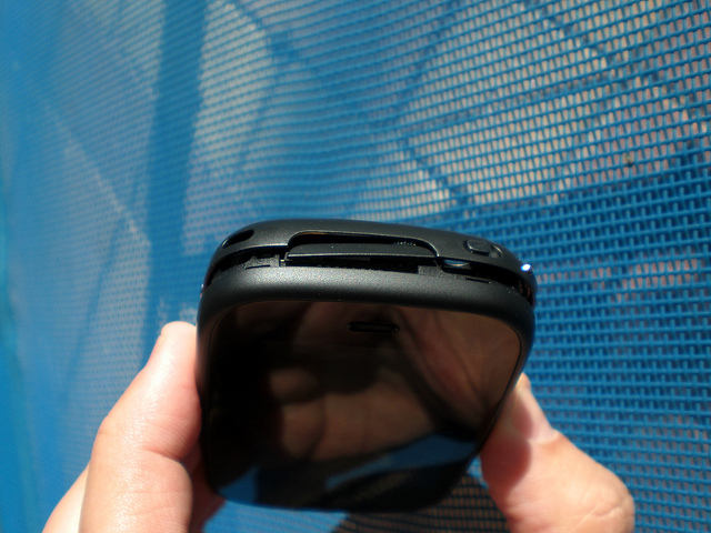
Initial upper half separation
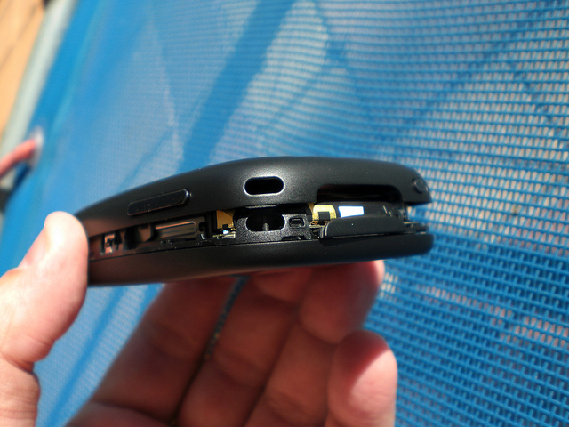
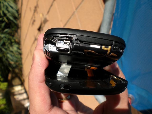
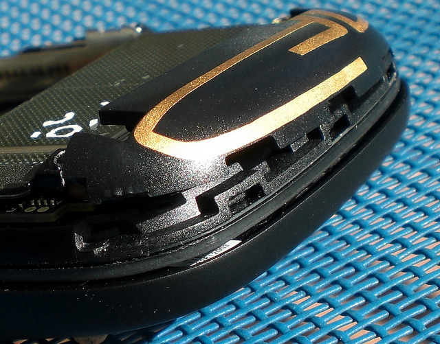
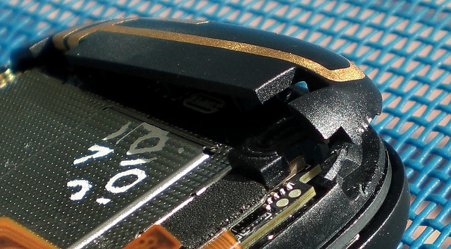
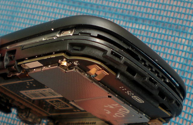
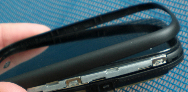
Now separate the plastic around the top of the phone, but do not pull it any further apart than this.
All the switches along the top of the device are part of the backplate.
Backplate separation achieved
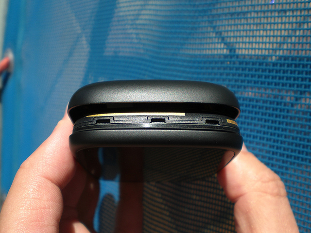
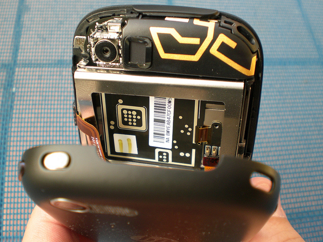
The backplate is now fully separated, but do not take it further than this at this stage.
In this shot you can see the lanyard attachment opening at the top left corner of the phone.
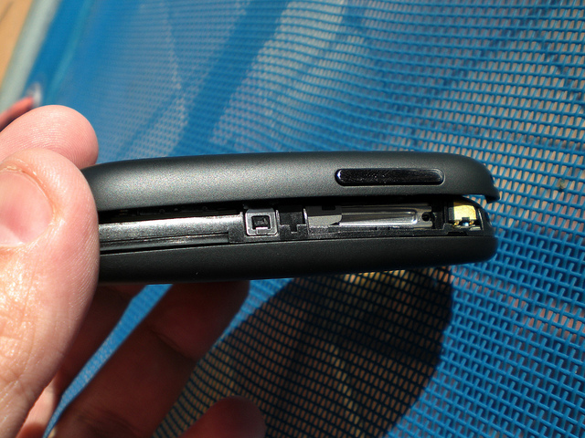
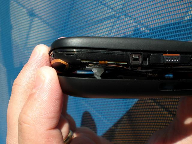
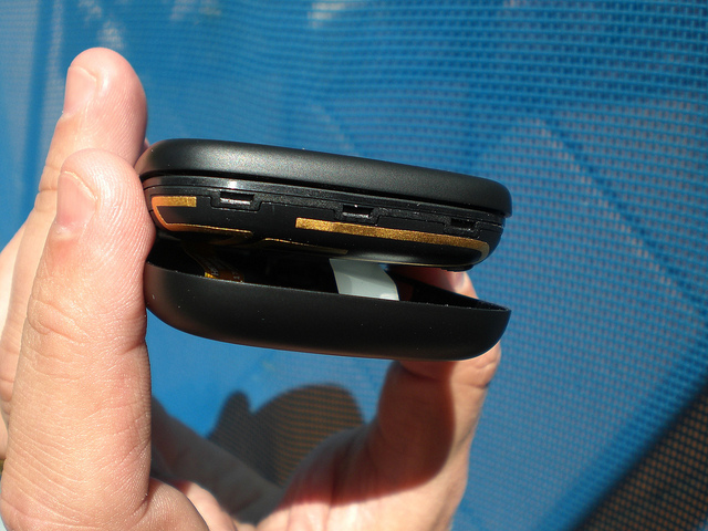
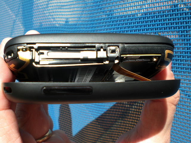
Here is the left-hand side of the phone.
Here is the bottom of the phone.
Here is the right-hand side of the phone.
Warranty sticker
Note the white warranty sticker between the backplate and the body of the phone. If this sticker separates from either the body or the backplate, your warranty is voided.
The tiny white rocker switch near the camera is the mute switch. The plastic slider which actuates this is part of the backplate.
Right-hand side.
Bottom.
Left-hand side.
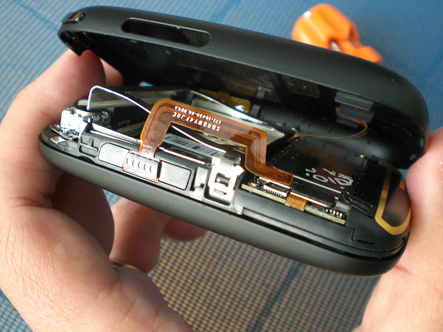
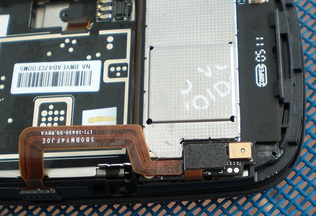
Here you can see the flex cable which connects the circuitry in the backplate (touchstone coil, touch to share, volume rocker, power switch) to the main body of the phone, somewhere underneath the battery.
Battery removal
It is possible to remove the battery without dislodging the white warranty sticker.
Voiding the warranty
Battery cage removal
Detach the magnetic connector flex cable, and then unhook the battery cage latch.
Here is the connector you need to detach before attempting to remove the battery cage.
Battery cage removed
Detaching the metal latch on each side allows the battery cage to be removed, exposing the location of the flex cable connector for the backplate connection.
Backplate separated
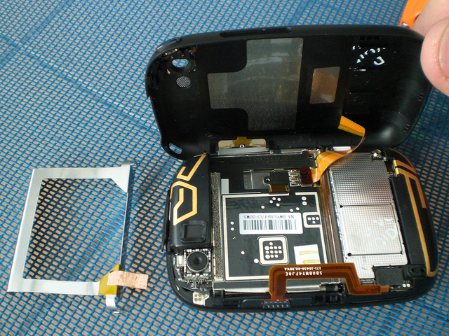
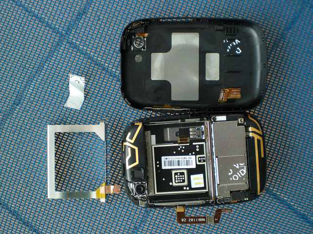
Detaching the flex cable allows the backplate to be completely separated from the body of the phone.
Speaker enclosure
Push on the black plastic area between the two metal tabs to release the inside edge of the speaker enclosure.
There are two plastic tabs which hook the top of the speaker enclosure to the body of the phone. If you lever up the inside edge (the edge in the battery compartment), then these two tabs unhook very easily.
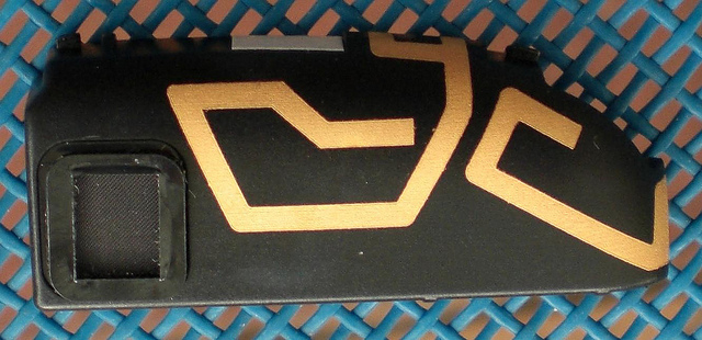
The front of the speaker enclosure.
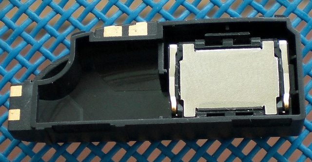
The rear of the speaker enclosure.
Underneath the speaker enclosure
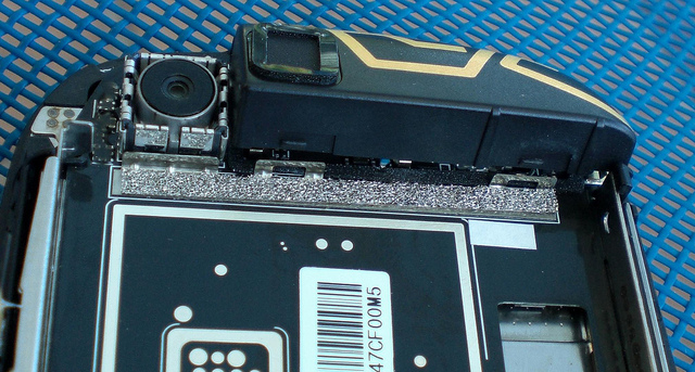
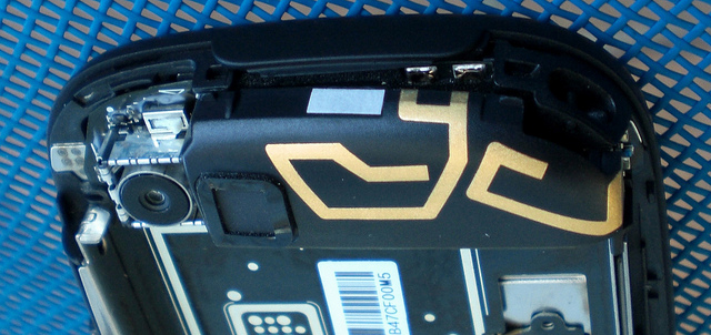
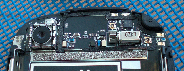
Underneath the speaker enclosure is the camera, the rocker switch for the ringer mute, the vibrator, and a couple of antenna connectors.
Rear cover close-ups
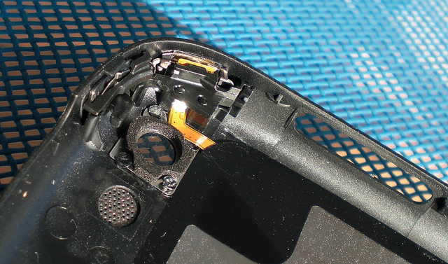
Close-up of the power switch and ringer mute slider.
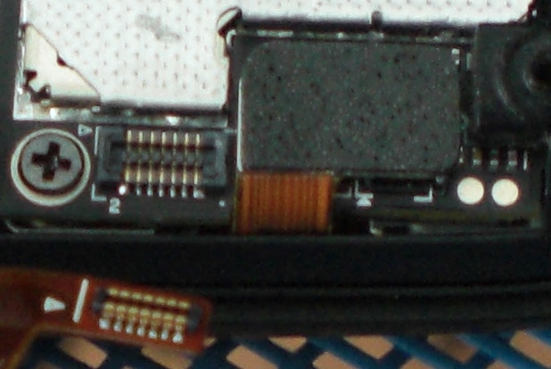
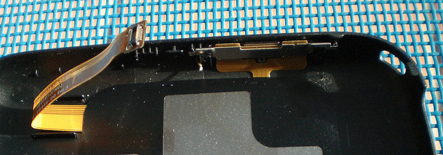
Close-up of the flex cable connector and volume rocker.
Battery close-ups
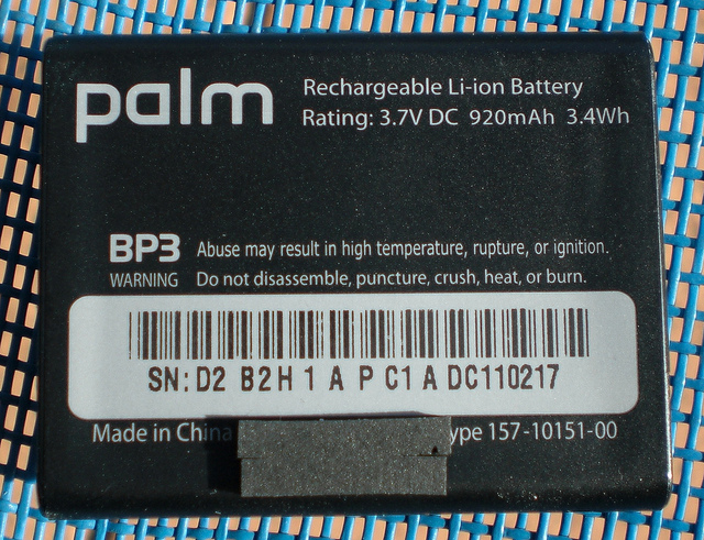
Front of the battery.
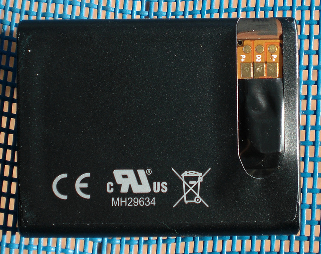
Rear of the battery. Terminals are P+, DQ, P- (left to right).
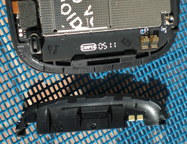
Lower antenna enclosure
These look like they may be tabs that hold on the lower antenna enclosure, but they are not.
This is the corner leverage point to unhook the lower antenna enclosure.
Lever it up from this side first.
The other side will come off easily.
Here is the detached lower antenna enclosure.
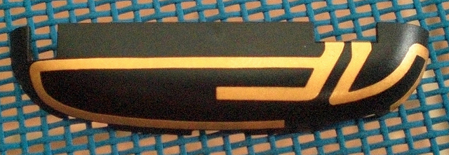
Front of the lower antenna enclosure.
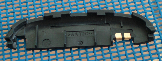
Rear of the lower antenna enclosure.
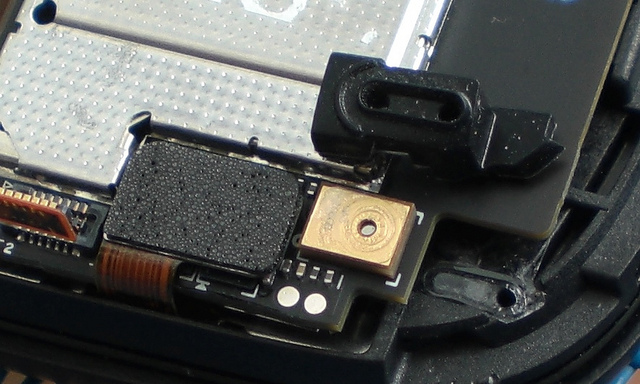
Microphone assembly
There is a piece of rubber which guides the sound from the front microphone around two corners to hit the gold coloured microphone.
Main circuit board
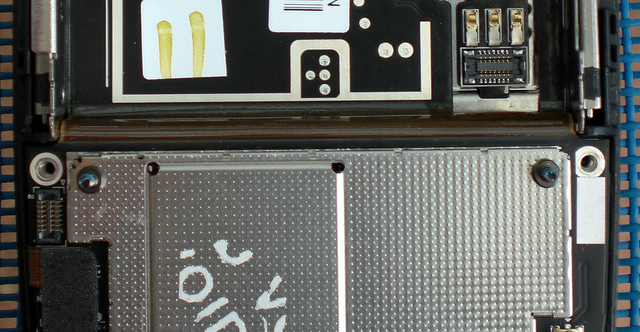
Two screws which hold down the lower half of the main circuit board.
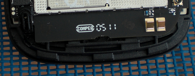
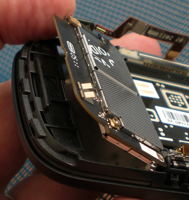
The lower half of the main circuit board can be raised by leveraging it away from the plastic clips at the bottom edge.
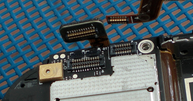
You also need to detach the flex cable that connects to the keyboard.
Unfortunately, it seems this part of the circuit board is not detachable, and is firmly connected to the rest of the circuitry in the battery compartment.
Looks like we need to find another way in ... so we clip everything back in place and start looking elsewhere.
Screen Bezel
An investigation of the other half of the device discovers a detachable screen bezel. In hindsight, this is obvious due to the existence of the white Veer model.
The bezel separates easiest from the keyboard end first.
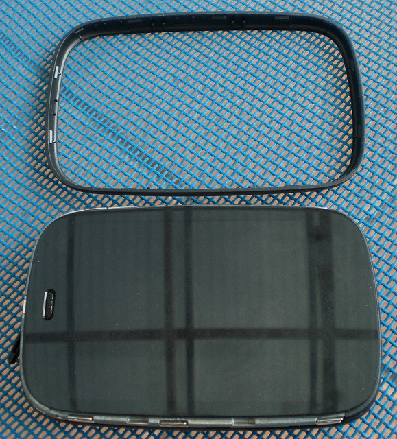
The detached screen bezel.
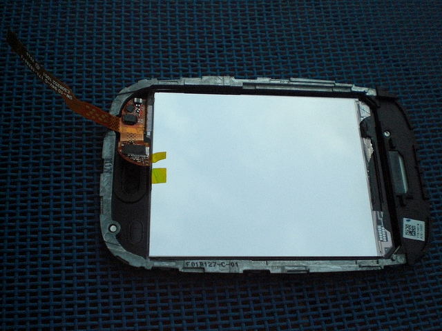
Removal of the bezel exposes some new metal clips to explore.
Screen Assembly
Three clips on one side of the screen.
Three clips on the other side of the screen.
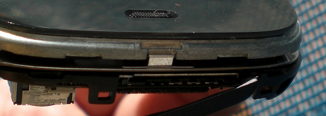
One clip at the top of the phone.
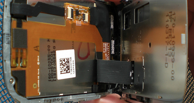
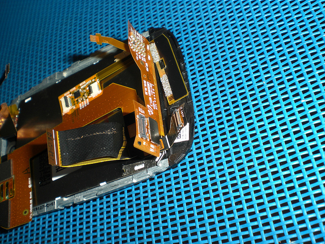
There is a flex cable connecting the screen assembly to the slider assembly. It looks fragile, so don't try and separate the screen from the slider assembly yet.
At this point, I reattached the screen assembly to the slider assembly, and decided to attempt to detach the circuit board from the slider assembly and attack the screen flex cable connection from that direction instead.
Detach Circuit Board
The circuit board can be detached by breaking the glued bond between it and the slider assembly.
WARNING: This is the point at which you are likely to damage something. If you are just "taking a look inside" you should stop at this point, as there is a real danger of damaging the main circuit board if you proceed past this point.
There are a number of places where the circuit board is bonded to the slider assembly. You can see those places in the next set of photos (they look like pieces of double sided tape on the rear of the circuit board and the rear of the slider assembly. It is not easy to break this bond - it requires a significant amount of force and ends up bending the circuit board to a degree where internal damage to the circuitry is very possible.
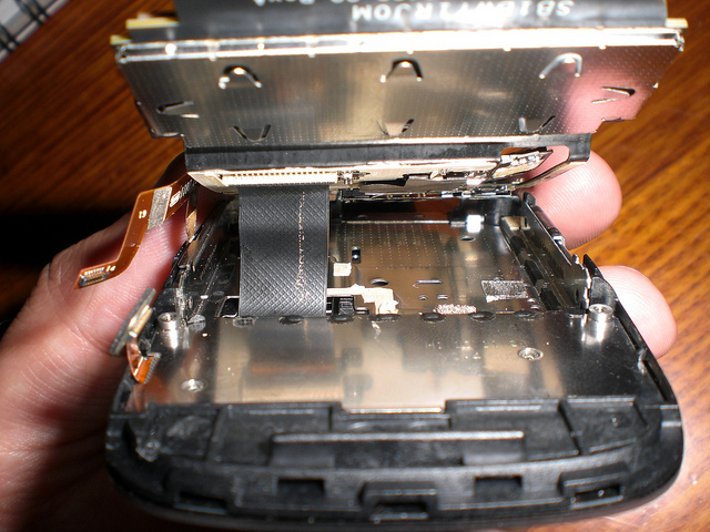
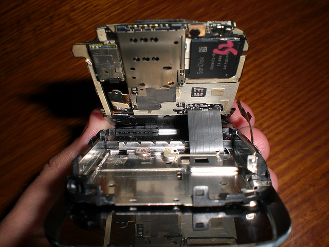
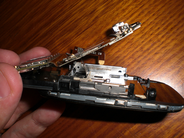
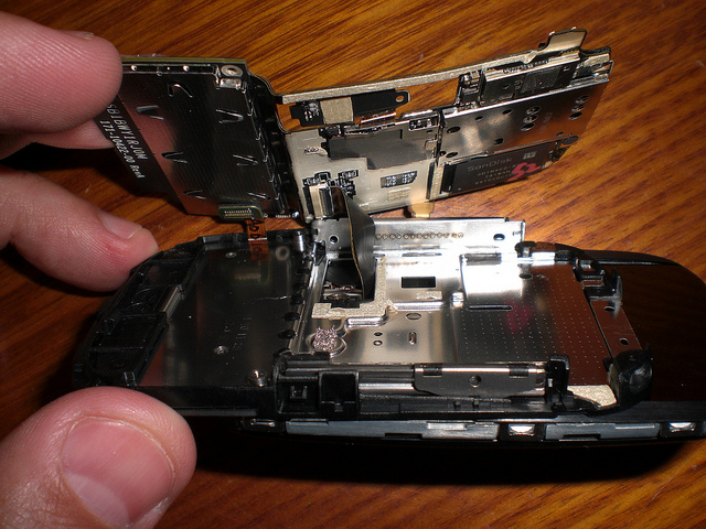
The next four shots show the circuit board separated from the slider assembly, but still attached to the screen via the flex cable.
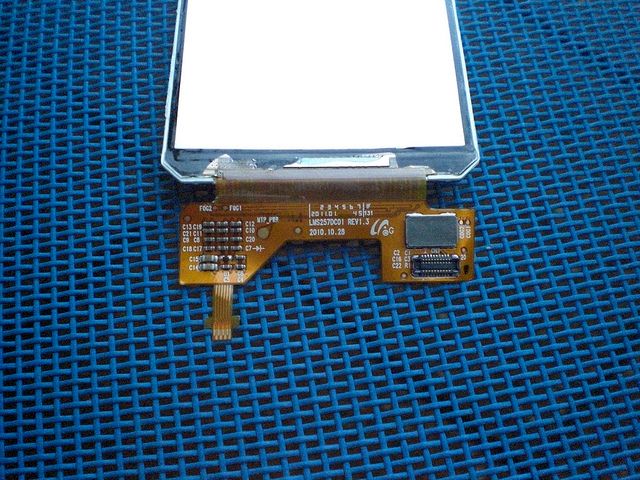
Bottom view of screen flex cable connection.
Top view of screen flex cable connection.
Side view of screen flex cable connection.
Side view of screen flex cable connection.
Separated Assemblies
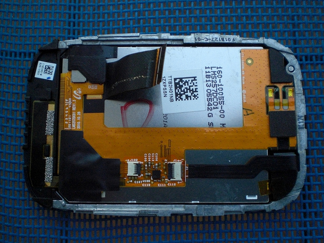
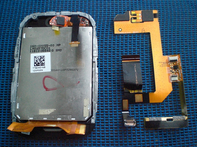
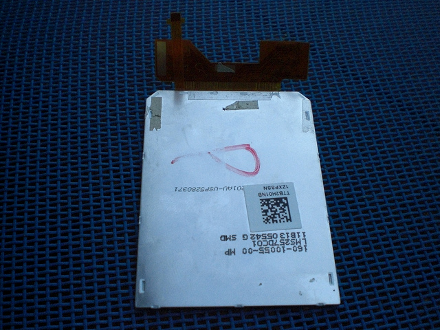
Rear of the screen assembly.
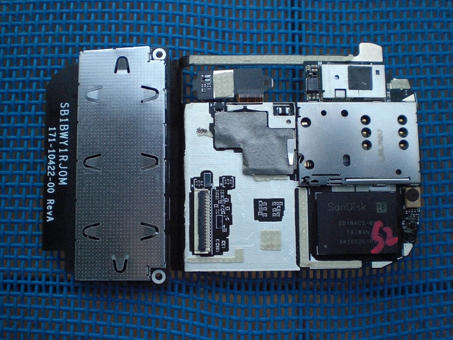
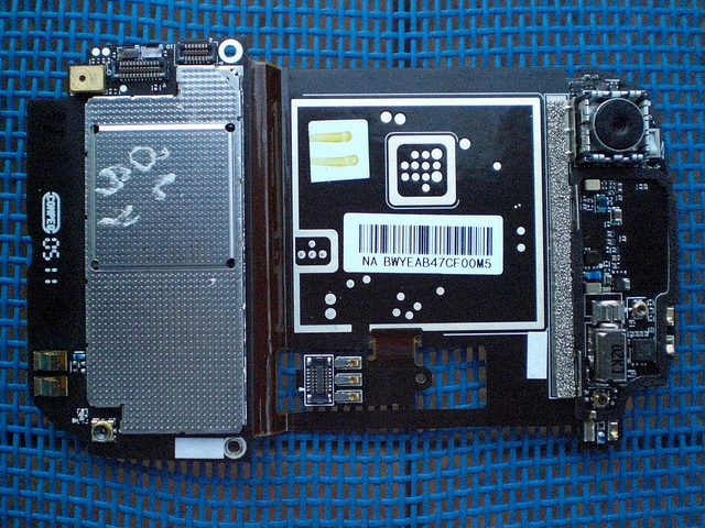
Rear of circuit board, normally glued to the slider assembly.
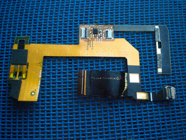
Front of the circuit board.
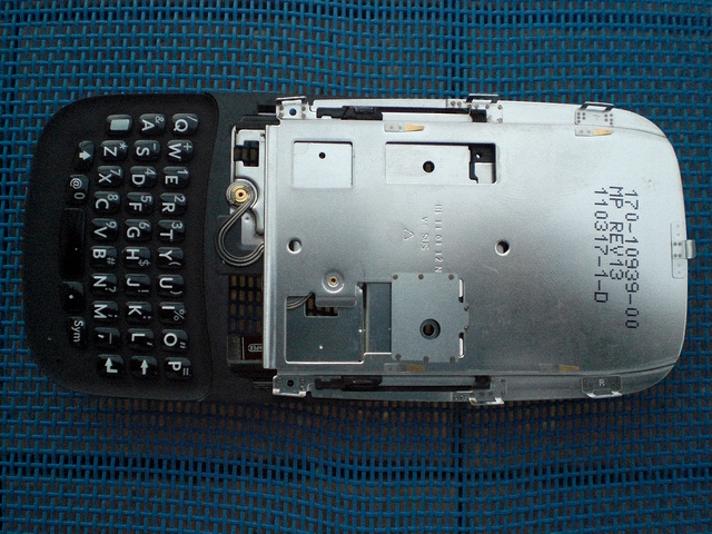
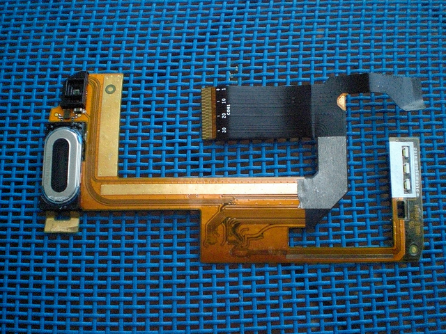
Front of the slider assembly.
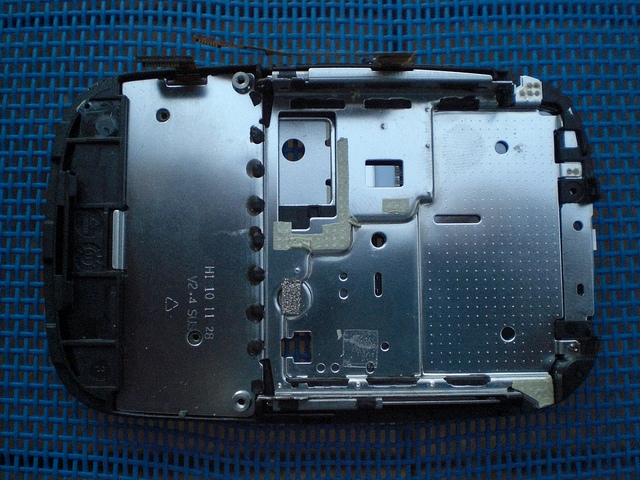
Rear of the slider assembly, where the circuit board sits.
Removing The Cans
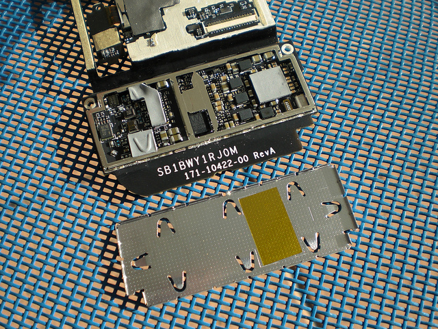
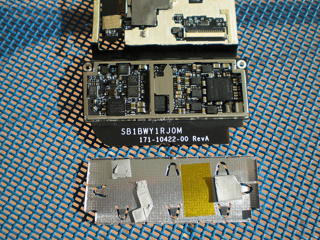
First can removed.
Heatsink material removed.
Display Subassembly
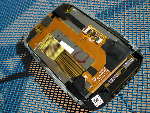
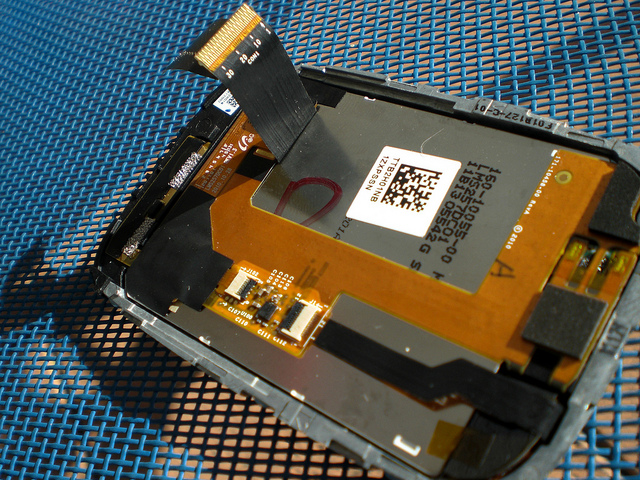
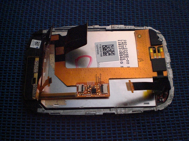
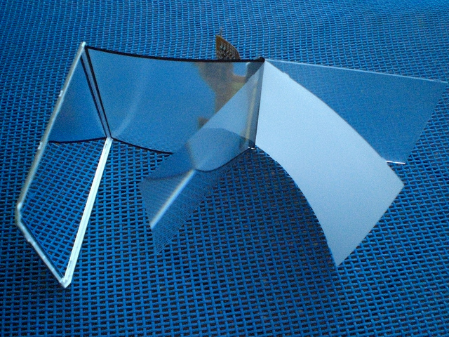
Inside the display flex cable.
The end of the display flex cable.
